A 5V USB power converter is connected to the Arduino board while the 4.5V power adaptor is connected to the power motor shield.
The Arduino system is connected to the switches via input pins (check code for exact numbering or use your own preference). The switches transmit the up/down signal (light fixture increase) and light fixture color temperature preference.
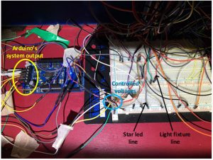
The power motor shield controls the voltage that is fed to the two connected outputs; one goes to that breadboard that supplies the LED stars and the other line two goes to the light fixtures on the scale model.
On the breadboard there are long, short and shorter jump wires that create rows having the same voltage, helping in hosting more than one LED line in parallel. Those rows are basically linked with the two different lines that are related with the two outputs, the star-line and the light fixture-line.
The software code interpreted the signal of the switches into increasing or decreasing the voltage signal to the two outputs leading to different voltages for stars and light fixtures with an inversely proportional relation. The following picture sums the aforementioned wiring description.